For controlling the RC-servos of Infanoid 1, 2, and 3, we developed Pico-1, the first motion controller. The main processor was Motorola 68HC11A1 (8bit CISC, 5MHz), communicating with the host PC via RS-232C at 9600bps, conrolling upto 4 RC-servos.
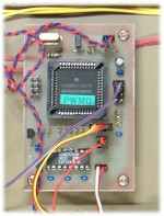
Pico-1 (1996) and a motion control box with Pico-1 (1997)
We also developed another program for controlling AC motor (with Harmonic Drive) by sending CW/CCW pulse to an off-the-shelf motor driver. The AC motor actuated the neck (pan/tilt) of Infanoid 3.
In the course of the software development for Pico-1, I first wrote an assembly program, then convert it into machine codes by hand (aka hand assemble), and finally transfer the codes to the on-board EEPROM (640byte). The total RAM size was only 256byte.
For building an upper-torso humanoid, Infanoid 4 and its followers, we needed a small motion controller that can handle DC motors with encoders. Also for controlling over 20 motors scattered over the body, we planned to embed a number of motion controllers and motor drivers inside the head, arms, and torso, in order to minimize the negative effects of cables.
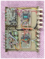
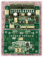
Prototypes of DC-motor controller Pico-11 and DC-motor driver Poco-32 (2000)
For this purpose, we developed Pico-11, whose main processor is Motorola 68HC11K4 (16MHz with OTP-ROM 24Kbyte + EEPROM 640byte + RAM 768byte). Pico-11 can control upto 4 DC motors with encoders. For reading encoders, it uses special function ICs (HCTL-2016). For communication, we developed a noise-tolerant low-impedance serial communication system. Assigning different addresses to different Pico-11s, maximum 127 Pico-11 nodes can be cascaded to form a linear communication line. Using JST/SH connectors, we made the PCB as small as 60mm×40mm, which is now the standard PCB size in CareBots Project.
The software of Pico-11 was written in Motorola assembly language and converted into machine codes by a standard assembler. Module by module, we wrote and assembled the source program, debugged on EEPROM (rewritable), and finally baked into OTP-ROM (one-time-programmable ROM). It was a laborious procedure.
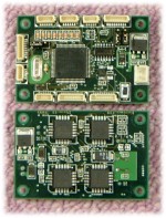
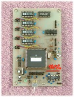
PCB-versions of Pico-11 and Poco-3 (front/back; 2000)
Meanwhile, we also developed a motor driver Poco-32 than can drive DC motors. It used LM18200 H-bridges, that allowed us to drive motors upto 40W and to sense the current going through the motors.
By the way, what do you guess why Pico-11? First of all, "11" comes from 68HC11, which is an offspring of 6809, the ultimate 8-bit microprocessor. Second, although "micro computer" is almost an obsolete word, "pico" is 1000000-times smaller than "micro". Then, why not "nano"? Well, "nano" has totally different connotations. Poco and Peco are phonetic variants of "pico".
For Infanoid 6, we planned to develop a motion controller and motor drivers with higher performance and low profile. Pico-2, a motion controller with 24bit encoder handling and higher control cycle, and Poco-14/42, high-density motor drivers, were the major outcome of our efforts.
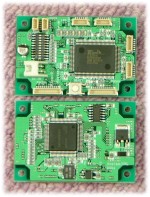
DC-motor controller Pico-2 (front/back; 2003)
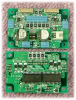
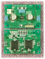
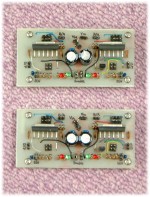
DC-motor driver Poco-14 and Poco-42 (front/back; 2003)
Poco-14 can drive upto 4 DC motors (upto 20W each). Poco-42 can drive upto 2 DC motors (upto 120W each). For H-bridges, we used STS's L6204D and L6201PS, respectively, located on the backside of PCBs for heat dissipation. Both have a current sensing capability.
Infanoid and Keepon are so-called "remote brain robot". The host PC is the brain for recognition and planning, and the robots are the body with sensors and actuators. The brain and the body are connected through asynchronous serial communication.
The first Pico, namely Pico-1, had an on-board RS-232C interface, so it could connect directly to the host PC. The second Pico, namely Pico-11, has a special TTL-level communication port, so it required some level conversion from conventional RS-232C signals. Peco-1 is the device for this level conversion, from RS-232C (3-line: TxD, RxD, SG) and low-impedance TTL (3-lines: T, R, GND). The impedance converson was done by utilizing open-collector drivers.
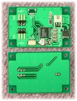
Peco-1 (front/back; 2000)
In the course of the development of Keepon, we first used Pico-11 and Poco-14 for controlling 4 motors. When we brought Keepon to field experiments, we found that this TTL-level communication (even with low-impedance drivers) was not enough to perform relatively long distance, high-speed communication. So we decided to switch to RS-485 (with 4-way = a pair of twist-pairs). The photos below illustrate how we modified the existing Pico-11 and Peco-1 to accommodate an RS-485 driver; this modification needed sort of micro surgery techniques.
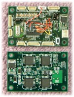
RS-485-versions of Peco-1 and Pico-11 (front/back; 2002)
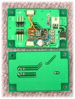
The motion controller Pico-2 has RS-485 communication ports that can be used for cascading connection. From the host PC, we first convert the RS-232C level into RS485 level to drive the communication line. One communication line can host upto 32 Pico-2. As in Peco-1, there are two independent level-conversion systems in a Peco-2.
Peco-2 (front/back; 2003)
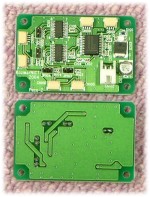
We are also developing WiFi-based communitation interface, Peco-3, that utilizes a CF WiFi card with a commercially available adaptor, ELZ-80C. We are also developing yet another wireless communication interface, Peco-4, that uses a Bluetooth device.
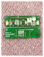
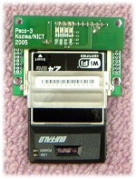
Peco-3 (front/back) and Poco-3 + EZL-80C (2005)