In order to encourage people who work on robotics for research, education, and walfare purposes, we are going to launch "Claybot", open robotic modules. So far, Claybot includes a motion controller board (Pico-2), motor drivers (Poco-14 and Poco42), and a communication interface (Peco-2). Each of the circuit boards has the size of 60mm x 40mm, which gives maximum flexibility to designing and building small robots.
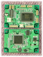
Pico-2, Poco-14, Poco-42, and Peco-2
(upper=front, lower=back)
- More on History of ClayBot
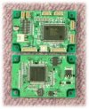
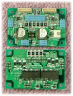
Pico-2 is a small, but versatile computer, especially suitable for conrolling DC motors with encoders. The size is just 60mm×40mm; thickness is about 10mm. The main processor is SH2 (32bit RISC; approx. 60MIPS at 50MHz clock; square shape) on the backside of the PCB for better heat dissipation. On the front side, it has a ZEN2044F (encoder interface IC; rectangular shape), LEDs, switches, and several connectors. The power connector is JST/XH (#1 is plus), and other connectors are JST/SH. Suppling power should be DC6V to 16V, typically 7.5V to 12V.
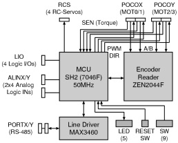
Pico-2 (its front/back sides and block diagram)
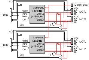
Being connected to the motor driver (Poco described below, for instance), Pico-2 can control up to four motors (MOT0-3) independently. Also Pico-2 can monitor the current going through the motor, which can be used for torque control.
- Download: Circuit diagram of Pico-2
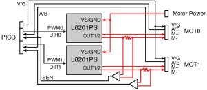
Each of the motors (MOT0-3) is controlled by PWM and DIR signals. The PWM signal has rectangular waves at 24KHz, whose duty ratio determines the average voltage applied to the motor. When DIR=0, the motor rotates CW (clockwise, when looking at the motor from the output shaft); when DIR=1, the motor rotates CCW (counter-clockwise). However, PWM and DIR signals cannot drive the motors directly; you need an H-brige (like that in Poco) to do that. When you sense the current going through the motor, you need to put a shunt register (0.1 to 1Ω), amplify the voltage appears at the register into the range of 0 to 5V, and feed it to SEN input terminal of Pico-2.
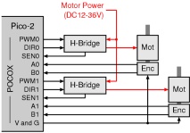
Connecting to motors and encoders
(same for POCOY terminals)
Pico-2 takes A and B signals from the encoders. For the internal computation, Pico-2 up-samples the A/B signals at the factor of four. This means, for example, a 100ppr (pulses per rotation) encoder will be 400 cpr (count per rotation) in Pico-2. Encoder's output can be either TTL-compatible or open-collector. Pico-2 has 5V power outlets (V and G) for encoders, so the encoders can stay alive when motor power supply is not present.
Pico-2 controls the motors under commands from the host PC. Communication with the host PC uses RS-485 serial communication with start-bit 1, data-bits 8, stop-bit 1, no-parity, 38400bps as the starndard. Most PC has RS-232C serial communication interface, whose signal can easily be converted into RS-485 (by using Peco-2 described below, for instance) for connecting to Pico-2. Using twisted pairs for R+/R− and for T+/T− of RS-485, noise tolerance will drastically be improved from RS-232C.
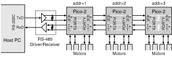
Connecting from the host PC
You can connect multiple Pico-2s using a single communication line. Each of the Pico-2 (called "node") on the communication line must have a unique address (5bits = 0 to 31), so that the host PC can identify each node by the address. Maximum 32 nodes can be connected to a single communication line to the host PC. The most distal node (from the host PC) should have its terminators enabled by setting SW8 and SW9; the RS-485 driver/receiver (next to the host PC) should also have its terminators enabled. These terminators are usually simple registers of 100 to 150Ω. On the other hand, the nodes in between the most distal node and the RS-485 driver/receiver should have its terminators disabled.
General I/O : Pico-2 has 4 digital input/output ports (LIO0-3; internally pulled up with 10KΩ) and 8 digital/analog input ports (ALINX0-3, ALINY0-3; no pull-up). These ports are not used in motor control, so you can use them for your own purposes.
RC-servo control: Pico-2 can control upto 4 RC-servos (inexpensive actuators for radio-controlled models). From RCS0-3 terminals, Pico-2 can output PWM signals with 10.667ms period and standard pulse width of 1.5ms, which work as the control signals for RC-servos. (You will need to supply power to the RC-servos separately, with the common ground to Pico-2.)
LEDs: Pico-2 has 5 LEDs (red). You can use them for displaying some internal states of the computation.
SW1-9: Pico-2 has 10 switches, among which SW1-5 (left most 5 switches) are open to users. Other switches have their own functions: SW6 enables flash-memory writing, SW7 is "boot" switch for downloading a new program, and SW8/9 are for enabling terminators on RS-485 lines. (SW10 is electrically disconnected from Pico-2.)
Pico-2 emits some heat mainly from the processor (SH2) and the voltage regulator (29M05). Both of the heat sources are on the backside of the PCB, so you can dissipate the heat to some heat sink (for example, the aluminum body of your robot) by thermally connecting them to the heat sink with some heat-conductive grease. (The height of SH2 is 3.0mm and that of 29M05 is 2.3mm.)
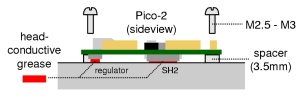
How to mount Pico-2 on your robot (with heat diffusion)
When you write a program for Pico-2, you should use the BIOS interface (described below) and compile your source program with a cross-compiler (for example, gcc). Then you burn the object program into the flash-memory of Pico-2. Having done them, Pico-2 gets ready to run your program.
- More on BIOS Interface of Pico-2
- More on SDK of Pico-2
BIOS (basic input/output system) is a collection of interface functions that allow your program to access the hardware resource of Pico-2. So far, BIOS of Pico-2 has the following interface functions. (Note: uchar = unsigned char; ushort = unsigned short; uint = unsigned int.)
-
PWM: DC motors (PWM, DIR)
- void PWM_init (void)
- void PWM_set (uchar numB2, short valW)
-
ENC: encoders (A, B)
- void ENC_init (void)
- int ENC_get (uchar numB2)
- void ENC_set (uchar numB2, int count)
-
SEN: current sensors (SEN)
- void SEN_init (void)
- ushort SEN_get (uchar numB2)
- void SEN_gets (ushort *sen0W, *sen1W, *sen2W, *sen3W)
-
SWT: on-board switches (SW5−1)
- void SWT_init (void)
- ushort SWT_get (void)
-
SCI: serial communication interface (PORTX, PORTY)
- void SCI_init (uchar addr, uchar pack_len, void *callback())
- void SCI_transmit (uchar *packet)
-
CMT: timer
- void CMT0_init (uchar cselB2, ushort periodW, void *callback());
- void CMT1_init (uchar cselB2, ushort periodW, void *callback());
-
RCS: RC-servos (RCS)
- void RCS_init (void)
- void RCS_set (uchar numB2, ushort valW)
-
LED: LED display (LED)
- void LED_init (void)
- void LED_set (ushort dataW5)
- ushort LED_get (void)
- ushort LED_op (ushort locW5, ushort dataW5)
-
LIO: digital input/output ports (LIO)
- void LIO_init (uchar dirB4)
- void LIO_set (uchar valB4)
- ushort LIO_get (void)
-
LIN: digital input ports (ALINX, ALINY)
- void LIN_init (void)
- ushort LIN_get (void)
-
AIX・AIY: analog input ports (ALINX, ALINY)
- void AIX_init (void)
- void AIX_gets (ushort *val0W, *val1W, *val2W, *val3W)
- void AIY_init (void)
- void AIY_gets (ushort *val0W, *val1W, *val2W, *val3W)
-
WDT: watchdog timer
- void WDT_init (uchar cselB3)
- void WDT_reset (void)
- int WDT_check (void)
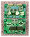
Poco-14 and Poco-42 are drivers for small-sized motors and mid-sized motors, respectively. Poco drives motors at the voltage/polarity according to the PWM/DIR signals from Pico-2. Poco takes a motor power supply (DC12V to 36V), which is usually separate from the power supply for Pico-2. Poco-14 drives upto 4 motors (maximum current 3A peak, 0.5A continuous) and Poco-42 drives upto 2 motors (maximum current 5A peak, 4A average); both can relay encoder signals (A/B) to and encoder power (V/G) from Pico-2.
Poco-14 (front/back) and its block diagram
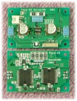
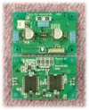
Poco-42 (front/back) and its block diagram
- Download: Circuit diagram of Poco-14
- Download: Circuit diagram of Poco-42
Both Poco-14 and Poco-42 has the same size as Pico-2 (60mm×40mm), with a thickness of 18mm (with motor connectors). Poco's H-bridges are at the backside of PCB, so the heat can easily dissipate to a heat sink. Poco uses same pin-assignment of connectors as Pico-2's; for motor connection, Poco uses 2×3 MIL connectors, whose pin assignment is described below. Please be aware of the connector direction.
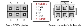
Pin assignment of the motor connectors
(left: from PCB-top; right: from Connector face)
Poco-14 has 4 pairs of jumper switches (SW3,4; SW5,6; SW9,10; SW11,12), which determines the sensitivity of current monitoring for MOT0, MOT1, MOT2, MOT3, respectively. Poco-42 has 2 pairs of jumper switches (SW2,3; SW5,6), which determines the sensitivity of current monitoring for MOT0 and MOT1, respectively. The current monitoring sensitivity will be set as follows. Please select appropriate sensitivity according to the size of the motor you use.
| Poco-14 | |||
|---|---|---|---|
| SW 3, 5, 9, 11 |
SW 4, 6, 10, 12 |
max current (A) |
sensitivity (V/A) |
| open | open | 0.3125 | 16.00 |
| short | open | 0.6250 | 8.000 |
| open | short | 0.9775 | 5.115 |
| short | short | 1.290 | 3.877 |
| Poco-42 | |||
|---|---|---|---|
| SW2, 5 | SW3, 6 | max current (A) |
sensitivity (V/A) |
| open | open | 1.364 | 3.666 |
| short | open | 2.728 | 1.833 |
| open | short | 4.278 | 1.169 |
| short | short | 5.642 | 0.8863 |
A 12-way cable with JST/SH connectors is used for the connection between Pico-2 and Poco. One cable (12-way) makes a connection for 2 motors. Pico-2 has POCOX and POCOY terminals for MOT0/1 and MOT2/3, respectively. Poco-14 has two similar terminals (PICOX, PICOY) and Poco-42 has one similar terminal (PICO). You can make an arbitrary combination of Pico/Poco connections.
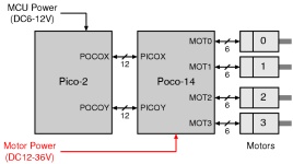
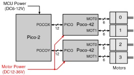
Connection examples of Pico-2, Poco, and motors
The major heat source of Poco is the H-bridges at the backside of the PCB. As in the heat dissipation method for Pico-2, you can paste the H-bridges on the aluminum body of your robot. (The height of Poco-14's H-bridge is 2.65mm; that of Poco-42 is 3.6mm.)
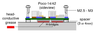
How to mount Poco on your robot (with heat diffusion)
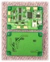
Peco-2 is a communication interface for bi-directional conversion between the host PC's RS-232C signals and Pico-2's RS-485 signals. Peco-2 does not do any flow control (such as RTS/CTS).
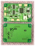
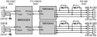
Peco-2 communication interface (appearance and block diagram)
- Download: Circuit diagram of Peco-2
For the connection to the host PC, we use a conventional serial cable with D-Sub 9 connectors. Please select appropriate connection from the diagrams below according to the serial cable (cross/straight) you use. In some cases, you may need to make a bridge between #7 and #8 pins of the RS-232C port of the host PC.
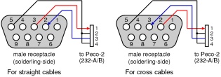
Serial connection from the host PC to Peco-2
For the connection to Pico-2, we use a 4-way cable with JST/SH connectors. Two ports on Peco-2, namely 485-A1 and 485-A2 are electrically same; also 485-B1 and 485-B2 are electrically same. A-line and B-line works independently. For example, you may stretch the RS-485 line in two different directions (e.g., to the left and to the right). In this case, enable the terminators on Pico-2s at the both ends of the lines and disable the terminators on Peco-2. Otherwise (when Peco-2 comes to one end of the line), enable the terminators on Peco-2 and those on Pico-2 at the other end of the line.